👑 Simple Royer Oscillator
0
Favorite
1
Copy
1729
Views

Circuit Description

Circuit Graph
This is the first circuit that I experimented with when I was fresh out of school.
It is to this day my favorite circuit.
Navigate to YouTube.com and do a search on "simple inverter", you will see this circuit everywhere!!!
I have not witnessed any Youtubers addressing the circuit, but it is indeed the Royer Oscillator.
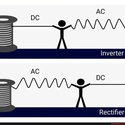
It is a simple switching circuit that uses a "quasi complementary push-pull Configuration" to drive a transformer.
This circuit functions by turning on one transistor before the other. This is because electrical components are not made exactly the same, there will be errors from component to component.
For this reason, it is crucial to note that it is very challenging to simulate a Royer Oscillator without saturating the transformer or running into different issues.
From experience, the frequency can be adjusted by changing the resistor values. Lowering the resistor values also lowers the frequency and vice versa is true. According to Wikipedia the output is a square wave, but they use a center tapped transformer with feedback windings which Multisim does not have at the moment. On my part the signal generated looks more like a dirty triangular wave full of noise. We will look at the output in another example. Also notice how our 12v input became 24V on the collector side. This circuit is also a voltage doubler. This is because the battery is in the middle of the 2 driving paths. The paths go in different directions and that causes their polarity to add up similar to batteries in series. One thing to recall is that transformers do not allow DC input to flow through. This circuit is basically fooling the transformer into thinking that the input is AC by creating a frequency with our switching circuit. This can also be seen in the flyback converter circuit where they use a Mosfet to switch a DC battery using coupled inductors. Most people that use this circuit just want to power normal AC loads like a lamp. For the transformer use a 50-60 Hetz 1 to 10 turns ratio transformer. Notice that you have to use the transformer in reverse direction. This means that the secondary side is now your primary side. Using a 12V battery on a 1:10 transformer would give us 120V "AC". This would be a great simple circuit to use if the power went out and you wanted to light up some lamps or to charge your cellphone.
*The output capacitor is NOT part of the circuit; we are using it to showcase the output voltage.
Creator

DannyJJ
144 Circuits
Date Created
2 years, 9 months ago
Last Modified
2 months, 3 weeks ago
Tags


Open Circuit
✕Circuit Graph
✕
There are currently no comments