7-segment display
A 7-segment display is a form of electronic display device that consists of seven LEDs arranged in a rectangular fashion. Each LED is called a segment that maps to one of the terminals A through G. By giving the proper binary-digit inputs to segments A through G, you can control the illumination of the segments, which allows you to display decimal numbers from 0 to 9 and letters from A to F.

The hexadecimal 7-segment display decodes 4 binary-digit inputs into a hexadecimal number which is displayed using the LED segments.

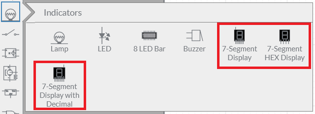
You can choose from the following 7-segment displays:

- 7-Segment Display—Standard 7-segment display with no decimal point (DP).
- 7-Segment HEX Display—Digital 7-segment display with no decimal point (DP), for displaying 4 data bits into hexadecimal.
- 7-Segment Display with Decimal—7-segment display with a DP that maps to terminal G. This one is useful when you want to display numbers greater than ten or decimal numbers by connecting two or more 7-segment displays.
Mapping
The following figure illustrates the mapping of the terminals (A through H) to the LED segments.

Truth table
The following table shows which segments to illuminate when you want to produce decimal digits from 0 through 9 and letters from A to F.
| Digit to display | A | B | C | D | E | F | G |
|---|---|---|---|---|---|---|---|
| 0 | 1 | 1 | 1 | 1 | 1 | 1 | 0 |
| 1 | 0 | 1 | 1 | 0 | 0 | 0 | 0 |
| 2 | 1 | 1 | 0 | 1 | 1 | 0 | 1 |
| 3 | 1 | 1 | 1 | 1 | 0 | 0 | 1 |
| 4 | 0 | 1 | 1 | 0 | 0 | 1 | 1 |
| 5 | 1 | 0 | 1 | 1 | 0 | 1 | 1 |
| 6 | 1 | 0 | 1 | 1 | 1 | 1 | 1 |
| 7 | 1 | 1 | 1 | 0 | 0 | 0 | 0 |
| 8 | 1 | 1 | 1 | 1 | 1 | 1 | 1 |
| 9 | 1 | 1 | 1 | 1 | 0 | 1 | 1 |
| A | 1 | 1 | 1 | 0 | 1 | 1 | 1 |
| b | 0 | 0 | 1 | 1 | 1 | 1 | 1 |
| C | 1 | 0 | 0 | 1 | 1 | 1 | 0 |
| d | 0 | 1 | 1 | 1 | 1 | 0 | 1 |
| E | 1 | 0 | 0 | 1 | 1 | 1 | 1 |
| F | 1 | 0 | 0 | 0 | 1 | 1 | 1 |
Common Anode (CA) and Common Cathode (CC) models
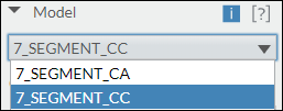
Each LED has two connecting pins: the anode and the cathode. In 7-segment displays, a common pin combines the anodes or cathodes of all LED segments and the remaining pins map to terminals A through G to represent each segment. You can configure the common pin to combine all the anodes or cathodes by selecting the Model in the Item tab of the configuration pane.

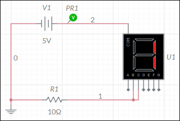
In the CA model, the COM terminal combines all the anode connections of the segments. To produce a display, wire the COM terminal to logic 1 or a high signal and wire the individual segments to logic 0 or ground. The following is an example of displaying 1 using the CA model.

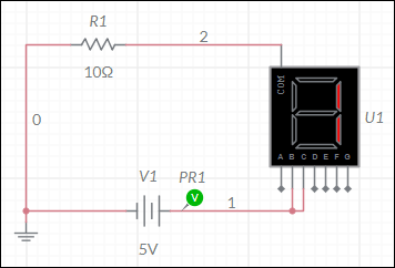
In the CC model, the COM terminal combines all the cathode connections of the segments. To produce a display, wire the COM terminal to logic 0 or ground and wire the segments to logic 1 or a high signal. The following is an example of displaying 1 using the CC model.

